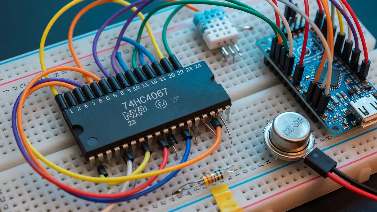
Guide: Getting Started with Multiplexers (74HC4067) for Extra Analog Inputs
Learn how to expand analog inputs on Arduino and ESP32 using the 74HC4067 multiplexer. Covers specs, wiring, code, common pitfalls, and comparisons.
Microcontrollers almost never give you enough analog inputs once your project grows beyond a handful of sensors. The 74HC4067 fixes that by letting you read 16 channels through a single ADC pin. Modules typically cost between $0.76 and $1.58.
Core Specifications
The chip is a 16-channel analog switch. A single common pin (Z) connects to any of the 16 channels based on a 4-bit address you set on the control pins. Here are the values that actually matter in practice:
- Supply voltage: 2.0–10 V (74HC version) or 4.5–5.5 V (74HCT version)
- On-resistance: roughly 80 Ω at 4.5 V, climbing toward 220 Ω at 2 V
- Bandwidth: 89 MHz
- Continuous current per channel: 25 mA
- Break-before-make time: about 6 ns
Signals must stay between ground and VCC. Anything outside that range will cause problems.
| Parameter | Value (typical) | Notes |
|---|---|---|
| Channels | 16 | Bidirectional |
| Ron @ 5 V | ~86 Ω | Increases at lower VCC |
| Max current | 25 mA | Per channel |
| Enable pin | Active low | Must be driven or tied low |
| Package options | SOIC-24, TSSOP-24, QFN | Breakouts widely available |
Pinout and Basic Wiring
Most breakout boards bring out VCC, GND, SIG (the common Z pin), four address lines (S0–S3), and EN. Tie EN to ground. You’ll need four GPIO pins for addressing and one ADC pin for the signal.
On an ESP32 or Arduino Uno the connections look like this:
- S0–S3 → any four digital outputs
- SIG → ADC input (A0 on Uno, GPIO 34 on ESP32)
- VCC/GND → board power rails
- Unused Y pins → 10 kΩ pull-down resistors to ground
Keep the analog traces short and away from fast digital lines.
Addressing Channels
Channel selection is straightforward binary. Here’s the pattern in Arduino code:
const int S[4] = {2, 3, 4, 5};  // S0–S3
const int SIG = A0;

void selectChannel(uint8_t ch) {
  for (int i = 0; i < 4; i++) {
    digitalWrite(S[i], (ch >> i) & 1);
  }
}
After you change the address, wait 100–500 µs before taking a reading. That pause prevents ghosting between channels.
Common Pitfalls and Fixes
Three issues show up again and again on forums:
- Crosstalk — Throw away the first sample after switching, or add a 200 µs delay.
- Floating inputs — Tie every unused channel to ground through a 10 kΩ resistor.
- 3.3 V operation — On-resistance rises, so keep sensor voltages inside the supply rails.
The EN pin must never be left floating. Tie it low or drive it directly.
Comparison with Alternatives
If you only need eight channels, the 74HC4051 uses just three address pins and has slightly lower on-resistance. For higher precision you can move to an I²C ADC such as the ADS1115, though it costs five to ten times as much as a 74HC4067 module.
| Device | Channels | Address pins | Typical Ron | Approx. price (module) |
|---|---|---|---|---|
| 74HC4067 | 16 | 4 | 80 Ω | $1 |
| 74HC4051 | 8 | 3 | 70 Ω | $0.80 |
| ADS1115 | 4 | I²C | N/A | $5–8 |
Practical Takeaways
Check the selected channel with a multimeter before you attach sensors. Test at the voltage you actually plan to run. On-resistance changes noticeably below 4.5 V. The RobTillaart HC4067 library can save time if you’re on an ESP32 and want higher-level functions. On a final board, consider adding series resistors on the sensor lines if fault current is a concern.
The 74HC4067 is still the cheapest way to get sixteen analog inputs as long as your speed and accuracy needs fit within its specs.