How to Calibrate Your 3D Printer for Perfect Dimensional Accuracy
Learn how to calibrate your Ender 3 for precise dimensional accuracy using a 20mm calibration cube, steps-per-mm adjustments, and shrinkage compensation.
Dimensional accuracy on an Ender 3 rarely happens by accident. Stock machines often ship with steps-per-mm values that leave a 20 mm cube measuring 19.6 mm instead. That tenth of a millimeter usually decides whether parts fit together or just sit close.
The 20 mm XYZ Calibration Cube
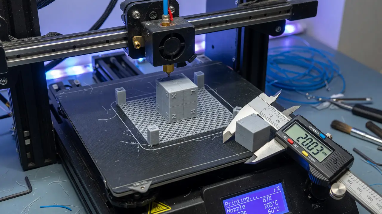
Print the standard 20 × 20 × 20 mm calibration cube with axis letters on each face. Use 0.2 mm layers, 20 % infill, and turn off cooling for the first two layers to reduce elephant’s foot.
Measure each axis in three spots with digital calipers, average the results, and note the numbers. After calibration you’re aiming for:
- X/Y: 19.95–20.05 mm
- Z: 19.90–20.10 mm
Anything outside ±0.2 mm almost always points to wrong steps-per-mm or mechanical binding.
Required Measurement Tools
You need 0.01 mm resolution calipers. Here’s a quick look at current options:
| Model | Resolution | Accuracy | Price (approx.) | Notes |
|---|---|---|---|---|
| Mitutoyo 500-196-30 | 0.01 mm | ±0.02 mm | $124–125 | Absolute scale, IP67 |
| Moore & Wright MW110 | 0.01 mm | ±0.03 mm | $51 | Solid mid-range choice |
| Clockwise Tools DCLA | 0.01 mm | ±0.03 mm | $25–35 | Data output, good value |
| Adoric (budget) | 0.01 mm | ±0.2 mm | <$15 | Plastic body, entry-level |
Skip the cheap plastic ones for final checks—their repeatability rarely beats 0.05 mm.
Updating Steps per mm on Marlin
The Ender 3 defaults are X = 80, Y = 80, Z = 400, E = 93. Once you have your measurements, use this formula:
new_steps = (expected_dimension / measured_dimension) × current_stepsExample (X axis measured 19.7 mm):
(80 × 20) / 19.7 ≈ 81.22
Send the new values through the menu or with G-code:
M92 X81.22 Y80.15 Z400.5
M500
Print the cube again and repeat until every axis lands inside the target window. Most people get to ±0.05 mm after one or two rounds.
Separating Steps Error from Shrinkage
After steps-per-mm are dialed in, any remaining undersize on PLA is usually shrinkage (0.2–0.5 %). Handle that in the slicer, not the firmware:
- PLA: scale the model to 100.3 % or set XY compensation to –0.3 %
- ABS: scale the model to 100.7 % or set XY compensation to –0.7 %
Don’t stack scaling on top of steps-per-mm changes—they fix two different problems.
Verification Workflow
The process follows a simple loop until your prints land inside tolerance. Here’s how it flows:
flowchart TD
    A[Print fresh 20 mm cube] --> B[Measure all axes & average]
    B --> C{Calculate new steps/mm}
    C --> D[Send M92 + M500]
    D --> E[Print second cube]
    E --> F{Within ±0.05 mm?}
    F -->|No| C
    F -->|Yes| G[Apply shrinkage compensation in slicer]
G --> H[Final verification print]- Print and measure a fresh 20 mm cube.
- Record the averaged dimensions.
- Calculate and apply the new steps-per-mm values.
- Print a second cube to confirm.
- Add shrinkage compensation only if the part is still consistently undersize after it cools.
Follow that order and you’ll typically drop from 0.3–0.6 mm deviation down to under 0.1 mm on all axes.
Final Takeaways
Accurate results on an Ender 3 come down to three things: measuring with 0.01 mm calipers, applying the steps-per-mm correction correctly, and handling material shrinkage separately in the slicer. Once those are sorted, functional fits stop being hit-or-miss.