CAN-Bus Reverse Engineering: How to Map Signals in Your Car Using Arduino
Reverse engineer your car's CAN bus with Arduino and MCP2515 to map signals like RPM and speed. Practical hardware, code, and workflow for custom projects.
Your car’s CAN bus carries every critical data point—RPM, speed, throttle position—yet manufacturers rarely publish the mappings. Reverse engineering these signals turns a generic OBD-II port into a precise data source for logging, dashboards, or custom controllers.
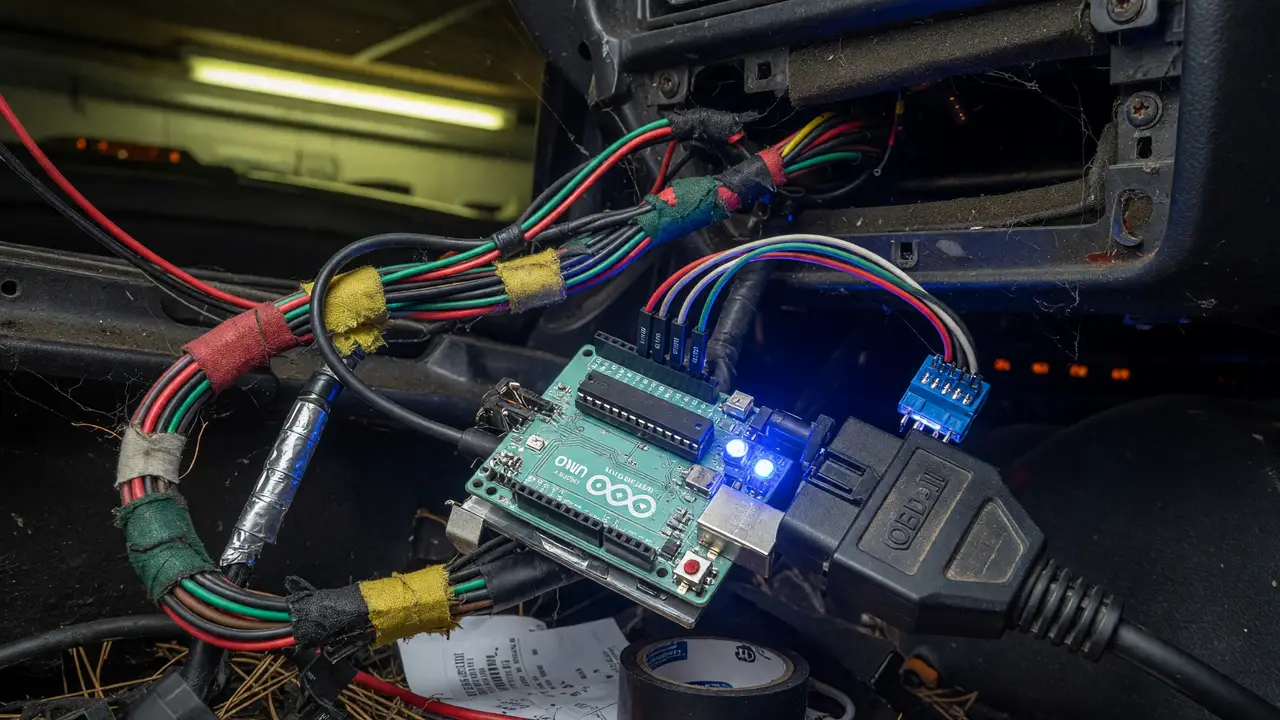
An Arduino paired with an MCP2515 shield gives you a low-cost way in. The same approach works across vehicles from VW Golf MK7s to 2016+ Toyotas, provided you work methodically.
Hardware Options Compared
Three Arduino-compatible modules show up in most projects. Your choice usually comes down to budget, connector quality, and how well the voltage range matches your setup.
| Module | Price | Transceiver | Voltage Range | Notes |
|---|---|---|---|---|
| Seeed Studio CAN-BUS Shield V2 | $21.99 | MCP2551 | 5 V | DB9 + screw terminals, OBD-II cable ready, Uno/Mega fit |
| Adafruit CAN Bus FeatherWing | $12.50 | TJA1051 | 2.7–5.5 V | Removable 120 Ω terminator, Feather ecosystem |
| Generic MCP2515 + TJA1050 | $2–3 | TJA1050 | 5 V | 8 MHz crystal, KF301 terminal, widely cloned |
The Arduino Uno remains the safest starting platform. Shields drop straight on and sketches compile without pin conflicts. Move to a Mega or ESP32 only after you have basic logging working reliably.
Recommended Stack and Library
Install the Seeed_Arduino_CAN library (v2.3.3) through the Arduino IDE Library Manager. It handles both classic MCP2515 controllers and newer FD variants while keeping the API straightforward for 11-bit and 29-bit frames.
Connect the shield to the OBD-II port with a DB9-OBD cable. OBD pins 6 (CAN_H) and 14 (CAN_L) map directly to the shield’s CAN_H/CAN_L terminals. Power the Uno from the car’s 12 V socket through a fused 5 V regulator or a USB power bank so you don’t flatten the battery during long sessions.
Capturing Raw Traffic
Start by logging everything on the bus. This minimal sketch prints ID, length, and payload to serial at 115200 baud:
#include <SPI.h>
#include "mcp_can.h"

MCP_CAN CAN(10);  // CS pin

void setup() {
  Serial.begin(115200);
  while (CAN.begin(MCP_ANY, CAN_500KBPS, MCP_8MHZ) != CAN_OK) {
    Serial.println("CAN init fail");
    delay(100);
  }
  Serial.println("CAN init OK");
}

void loop() {
  long unsigned int rxId;
  unsigned char len;
  unsigned char buf[8];

  if (CAN.readMsgBuf(&rxId, &len, buf) == CAN_OK) {
    Serial.print("ID: 0x"); Serial.print(rxId, HEX);
    Serial.print("  Len: "); Serial.print(len);
    Serial.print("  Data:");
    for (int i = 0; i < len; i++) {
      Serial.print(" 0x"); Serial.print(buf[i], HEX);
    }
    Serial.println();
  }
}
Drive normally for a few minutes while you capture. Save the output to CSV or drop it straight into SavvyCAN for filtering.
Mapping Signals with Public DBCs
Raw IDs by themselves tell you almost nothing. Cross-reference what you captured against open DBC files from Comma.ai’s OpenDBC repository or the awesome-automotive-can-id collection.
- VW Golf MK7 (MQB platform) often uses ID
0x0B4for engine RPM on the drivetrain bus. - 2016+ Toyota models (Camry, RAV4) send vehicle speed on the radar CAN bus at ID
0x0B4with a 0.01 km/h scaling factor.
Load candidate DBC files into SavvyCAN, filter by known signals, and check the decoded values against the dashboard. Tweak byte order and scaling until the numbers line up with the instrument cluster.
Workflow for Safe Reverse Engineering
Here’s the practical sequence most people follow:
flowchart TD
    A[1. Connect to OBD-II] --> B[2. Log raw frames]
    B --> C[3. Import to SavvyCAN]
    B --> D[Verify 500 kbps]
    C --> E[Apply public DBC]
    D --> F[Filter high-frequency IDs]
    F --> G[4. Drive and correlate]
    G --> H[5. Extract scaling and endianness]
    H --> I[6. Create custom DBC]
Always work in a safe location. Disconnect the shield before any service that could trigger airbags or stability systems.
Key points
- Start with the Seeed shield on an Uno for the best connector options and broad compatibility.
- The cheap $2–3 modules are fine for bench testing but rarely hold up well on the road.
- Combine your captured data with existing DBC files instead of decoding every byte from scratch.
- Log at 500 kbps first. Only switch speeds if the vehicle actually uses a different bus rate.
Follow the steps above and you can usually build a usable signal map in one afternoon of driving and analysis. The resulting DBC file then works across the same model years and becomes the base for any custom CAN project you build later.