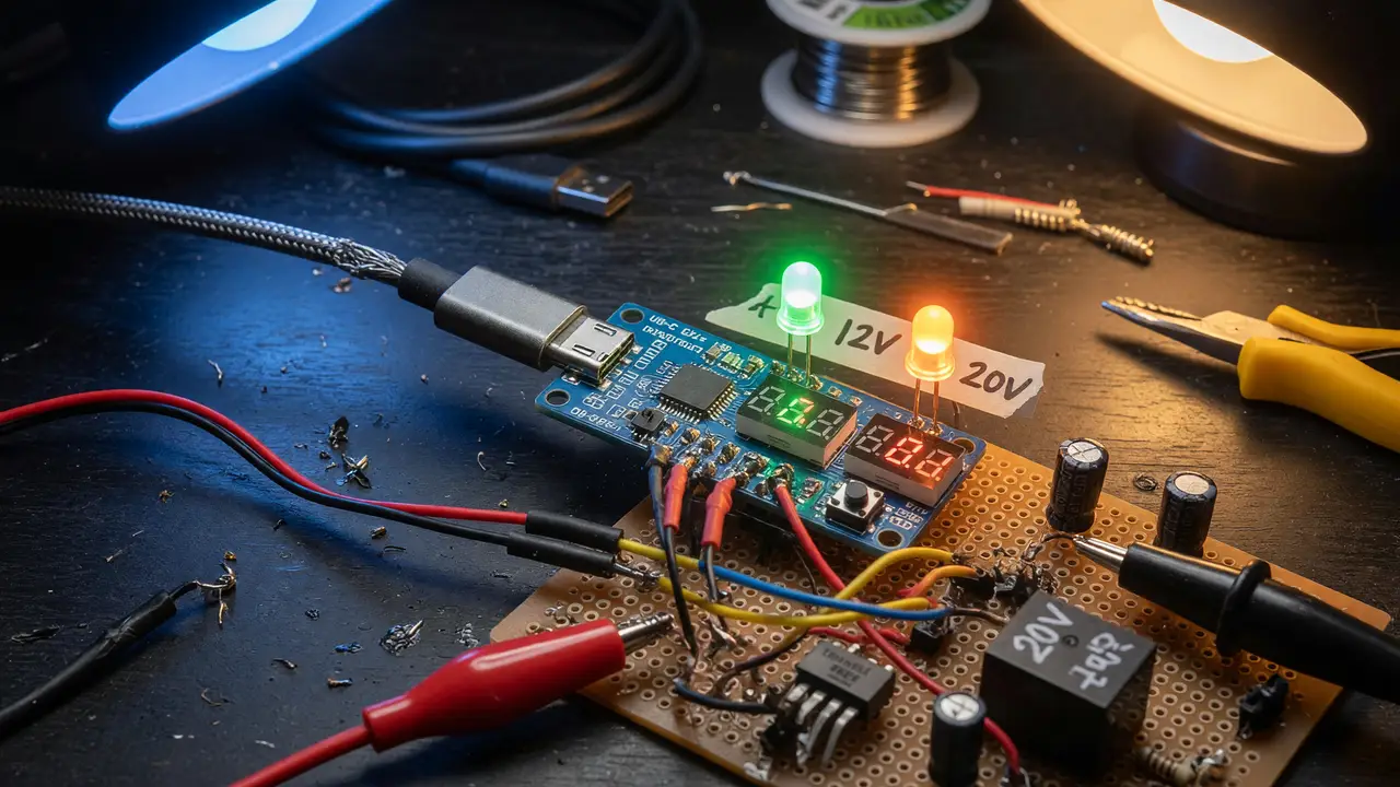
DIY USB-C PD: How to Pull 12 V / 20 V Directly to Your Project
USB-C PD trigger boards like ZY12PDN, CH224K, and IP2721 let you pull 12V or 20V directly from chargers. Compare options, wiring tips, and safety for your projects.
USB-C Power Delivery turns ordinary chargers into flexible bench supplies. Most projects still need 12 V or 20 V rails though, not the default 5 V. PD trigger boards handle that gap. They negotiate the higher voltage profiles over the CC lines and pass the requested voltage straight through.
What a PD Trigger Board Actually Does
A trigger board sits between a USB-C source and your load. It acts as a sink, requests a specific voltage from the charger’s Source_Capabilities message, and then routes that voltage to the output pads. No buck or boost circuitry is involved—the board only manages the PD handshake.
Three chips show up on most modules: the STM32-based ZY12PDN, the WCH CH224K, and the IP2721. All three handle the standard fixed PDOs up to 20 V and drop back to QC or BC1.2 when a PD source isn’t available.
Head-to-Head Comparison
| Board | Price (Sep 2024) | Voltage Selection | Max Current | Size (mm) | Standout Feature |
|---|---|---|---|---|---|
| ZY12PDN | $1.80–$2.54 | Button + RGB LED | 5 A | 31 × 15 × 4 | On-board voltage cycling |
| CH224K | $2–$4 | Resistor or logic pins | 5 A | ~20 × 12 | Fixed-voltage simplicity |
| IP2721 | $1.31–$3.52 | Fixed or jumper | 5 A | Cable-style | Easy pigtail integration |
All three accept 4–22 V on VBUS after negotiation. Sustained 5 A operation requires an E-Mark cable.
Recommended Modules for 20 V Projects
Three options keep coming up in discussions on Reddit, EEVblog, and Dronebotworkshop:
- ZY12PDN — Best when you need to switch voltages during development.
- CH224K modules — Lowest parts count when the voltage is known in advance.
- IP2721 pigtails — Cleanest mechanical solution for permanent installs.
Pair any of them with a 65 W or larger charger that actually advertises 20 V at 3 A or more. Otherwise the source will reject the request or current-limit.
For the CH224K, voltage is set with resistors on the CFG pins. A common arrangement looks like this:
# CH224K 20 V example
CFG1: 10 kΩ to GND
CFG2: 22 kΩ to GND
CFG3: open
Safe Current Limits and Failure Modes
Boards often carry a “100 W” label, but the real limits come from the charger’s PDO and the cable. A 3 A cable tops out around 60 W. Continuous 5 A at 20 V needs a 5 A-rated E-Mark cable and a source that supports the 20 V / 5 A PDO.
Common problems reported by users include:
- Inductive kick on sudden load disconnect destroying the CH224K CC pins
- Requesting 20 V from a 45 W charger that can only supply 2.25 A
- Voltage spikes on the CC lines from cheap cables
Add a flyback diode across inductive loads and a TVS on VBUS whenever the project pulls more than a few amps.
Practical Wiring and Testing Steps
- Plug the trigger board’s USB-C receptacle into your charger.
- Check the output pads with a multimeter to confirm the requested voltage appears.
- Solder or screw your load directly to the VBUS and GND pads—never rely on the USB-C shell for high current.
- For fixed-voltage designs, pick the CH224K and set the CFG resistors once. For bench work, keep the ZY12PDN and its button.
These modules remain the cheapest reliable path to 12 V and 20 V rails from any modern USB-C wall adapter.