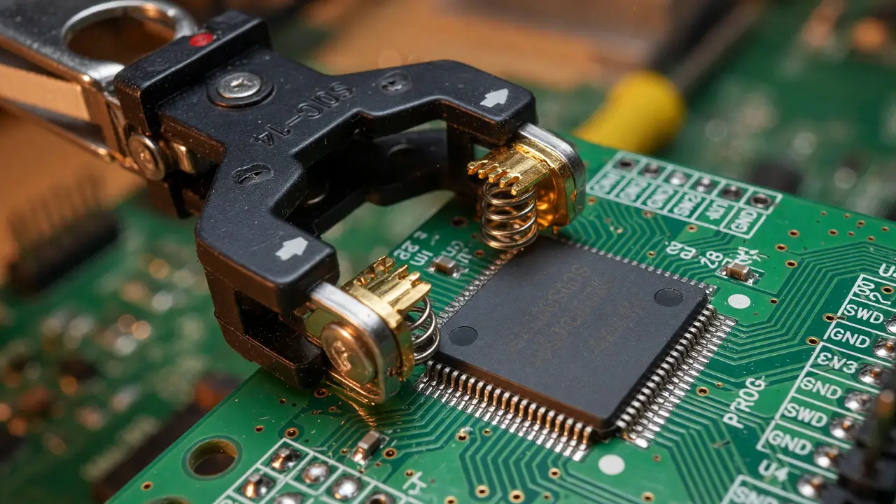
Guide to SOP14 Programming Clips: Flashing Chips Without Desoldering
Learn how to use SOP14 programming clips to flash firmware without desoldering chips. Tips for in-circuit EEPROM and MCU programming, clip selection, and reliability.
Desoldering an SOP14 package risks lifted pads and damaged boards. A programming clip lets you read and write firmware in-circuit, provided the pins are accessible and the rest of the board stays quiet during the operation.
SOP14 Package Basics
An SOP14 part has 14 leads on a 1.27 mm pitch. The body is usually 3.9 mm wide (narrow body) or 4.4–7.8 mm, with an overall length of 10.2–10.8 mm. Clips grip these leads with spring contacts and break the signals out to a standard 2.54 mm DIP-16 header.
Most clips are built for 3.3 V or 5 V logic. They have no high-voltage programming pin, so the target chip must already be powered at its normal operating voltage.
Current Pricing and Sellers
Generic Chinese SOP14/SOP16 probes fill the low-cost end. Pomona clips run two to three times higher but give stronger contact force and last longer.
| Product | Typical Price (USD) | Source | Notes |
|---|---|---|---|
| Generic SOP14 probe | 11–12 | AliExpress | 40 % discount listings common |
| Pomona 5251 (14-pin) | 17–34 | AliExpress/Mouser | Multiple sellers, variable stock |
| SOIC8 clip (baseline) | 3–6 | AliExpress | 2–4× cheaper than SOP14 |
| FSHH SOP14-to-DIP socket | 13–60 | Specialist catalogs | Clamshell style, higher reliability |
Digi-Key currently carries no dedicated SOP14 clips, so most people buy from AliExpress or Mouser.
Compatible Devices
Clips see the most use on:
- 24/25/93-series EEPROMs and flash
- PIC mid-range microcontrollers via ICSP
- STM8 and some STM32 parts when paired with an ST-Link V2
- Legacy AVR devices in 14-pin SOP packages
Success depends more on board layout than on the silicon family. Short traces, low bus capacitance, and no powered peripherals drawing current during the operation all help.
Workflow for In-Circuit Programming
flowchart TD
    A[Power board down] --> B[Attach clip, verify pin 1]
    B --> C[Connect programmer header]
    C --> D[Isolate target VCC if possible]
    D --> E[Run read/verify cycle]
    E --> F[Write firmware]
    F --> G[Power cycle and confirm]
Keep adapter cables under 10 cm. Longer wires add inductance and raise the chance of read/write errors. Many people also lift the board’s main supply or add a series diode so other components don’t load the programmer’s outputs.
Reliability Trade-offs
Forum threads on EEVblog and Reddit show mixed results. Cheap clips often slip or make intermittent contact on the narrow 3.9 mm bodies. Pomona models reduce that problem but still need the target fully powered down. When surrounding circuitry can’t be isolated, dedicated ISP headers or clamshell sockets are usually more reliable for repeated work.
Practical Checklist
- Confirm body width before ordering (3.9 mm vs wider variants).
- Use an external supply or current-limited programmer output.
- Verify pin 1 orientation twice—SOP14 pinouts are easy to reverse.
- Start with a read-and-verify pass before any write operation.
- Keep a set of micro-grippers handy for non-standard or obstructed pinouts.
SOP14 clips fill a narrow but useful niche for legacy recovery and field updates. When contact is solid and the board can be isolated, they remove the desoldering risk. For production runs or difficult layouts, socketed adapters remain the better choice.