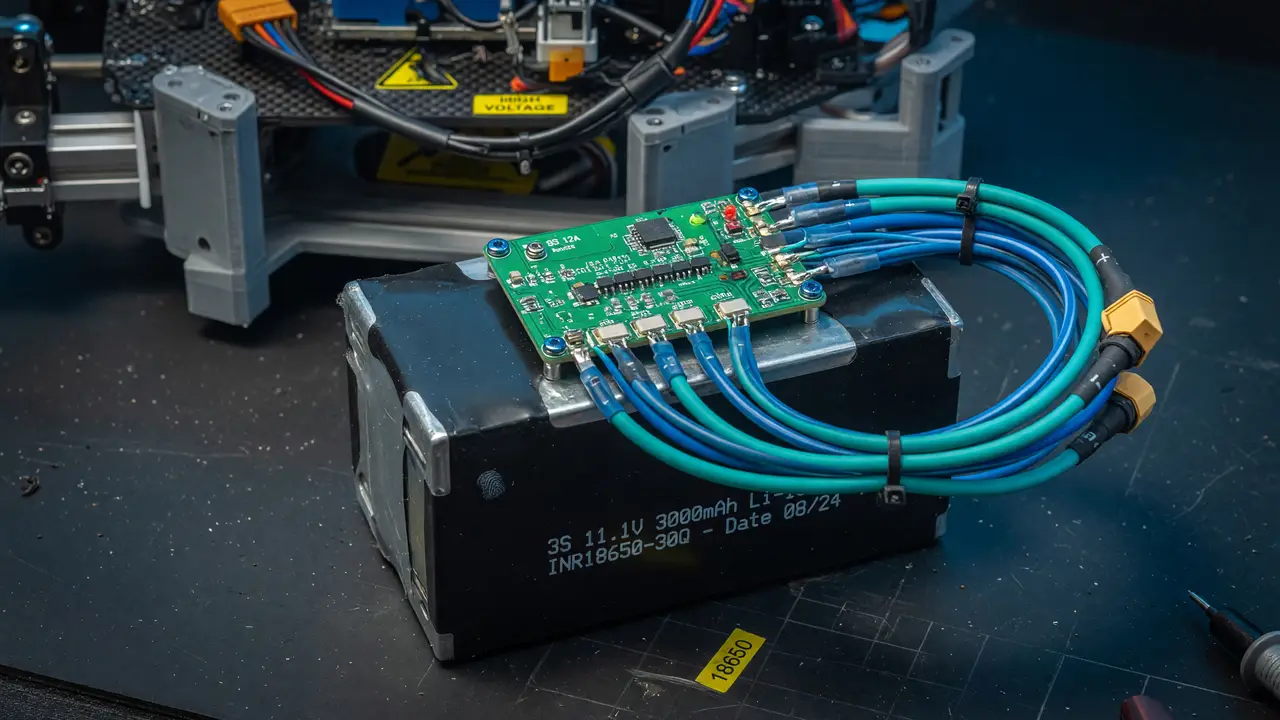
Demystifying BMS: How to Safely Wire a 3S Li-ion Battery Pack for Your Robots
Learn how to safely select, wire, and protect a 3S Li-ion pack with BMS for robotics. Covers voltages, module choices, pinouts, thresholds, and failure prevention.
Li-ion packs give robots strong performance without extra weight, but one bad connection or weak protection circuit can kill cells or shut everything down mid-run. A Battery Management System (BMS) avoids those problems when you pick the right module and wire it properly.
Voltage Specifications Every Builder Must Know
A 3S pack stacks three 18650 cells in series. You get 11.1 V nominal, 12.6 V at full charge, and a safe discharge floor between 8.4 V and 9.0 V (2.8–3.0 V per cell). Anything below 2.5 V per cell risks permanent damage from copper shunting.
Most robotics builders stick with the 3.0 V cutoff to keep cells healthy over many cycles. Check voltages with a multimeter before the first charge.
Selecting a BMS Module for Robotic Loads
Plenty of generic 3S boards sit on the market, yet their published current ratings often fall short in real use. The table below summarizes common options drawn from recent listings and builder feedback.
| Module Type | Continuous Current | Balance Current | Price Range | Notes for Robotics |
|---|---|---|---|---|
| Generic HX-3S-01 | 12–20 A | 30–90 mA | $1.27–$3.50 | Derate heavily; suitable for small bots |
| 25–40 A with heatsink | 25–40 A | Passive | $1.94–$5.45 | Common choice; test actual limits |
| JBD / high-current | 50–80 A | Passive | $14–$24 | Better MOSFETs; fewer failures |
Plan on at least 1.5× your expected peak draw. Modules with temperature sensing are worth the small extra cost.
Wiring Sequence and Pinout
Follow the right order and you avoid most assembly headaches. Typical 3S BMS pinouts look like this:
- B–: Pack negative
- B1: Cell 1–2 junction
- B2: Cell 2–3 junction
- B3: Cell 3 positive
- P–: Load negative output
- P+ / B+: Pack positive (direct feed to ESC)
flowchart TD
    A[Connect balance wires first:<br/>B– → B1 → B2 → B3] --> B[Attach thick B– to pack negative]
    B --> C[Connect B+ to pack positive]
    C --> D[Verify voltages:<br/>0 V / 4.2 V / 8.4 V / 12.6 V]
    D --> E[Connect P– to ESC negative]
    E --> F[Take positive directly from B+]
Double-check the balance-tap voltages before you attach the load. Some boards also need a quick “kickstart” charge after they trip into protection.
Protection Thresholds and Standards
Good BMS boards hit these limits:
- Over-voltage trip: 4.25–4.35 V per cell
- Under-voltage cutoff: 2.7–3.0 V per cell
- Short-circuit response: <200 µs
- Over-current: 100–200 % of rated value within 5 ms
Look for hysteresis on recovery and cell monitoring within ±5 mV. Standards like IEC 62619 and UL 1642 give useful reference timings.
Common Failures and Practical Mitigations
Cheap MOSFETs often fail at 25–50 % of the claimed current. Motor startup spikes can trip protection even on boards that should handle the load. Passive balancing resistors also run warm, and tight enclosures make things worse.
Builders who have been through this usually suggest:
- Derating cheap boards by 30–50 %
- Adding a soft-start resistor for capacitive loads
- Stepping up to JBD or DALY modules for competition robots
Always test the finished pack under realistic load before you install it.
A properly wired 3S BMS keeps cells safe, stops sudden power cuts, and stretches pack life. Check voltages at every step, derate where needed, and pick modules with clear protection specs. Those steps turn the battery from a weak point into something you can count on.