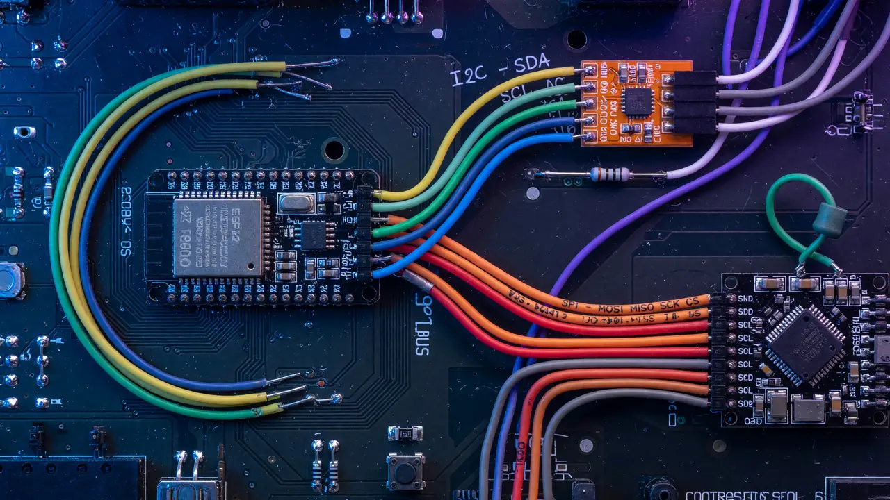
I2C vs SPI: Protocol Comparison for Sensors
Compare I2C and SPI for sensor integration: speed, wiring, power, device limits, failure modes, and practical guidelines for choosing the right protocol in prototypes.
Clock Speed Realities
I2C handles most sensors at moderate rates without trouble. Standard mode tops out at 100 kHz, fast mode reaches 400 kHz—the everyday choice—fast-mode plus hits 1 MHz, and high-speed mode claims 3.4 MHz. Few sensor datasheets actually enable those faster options.
SPI has no built-in ceiling. Sensors commonly run 1–10 MHz, and clean PCB traces can push 50 MHz. The ICM-20602, for instance, supports 10 MHz on SPI while its I2C side stops at 400 kHz. The real limit almost always sits in the MCU peripheral rather than the protocol itself.
An 8-bit Arduino with untuned SPI rarely exceeds 8 MHz, which narrows the gap with a solid 400 kHz I2C bus.
Wiring and Device Count
I2C uses just two wires—SDA and SCL—plus pull-ups. Seven-bit addressing can theoretically reach 127 devices, yet bus capacitance (capped at 400 pF in fast mode) usually restricts practical builds to 8–20 sensors before rise times become unreliable.
SPI needs three shared lines (MOSI, MISO, SCLK) plus one dedicated chip-select per device. One sensor takes four wires; ten sensors take thirteen. Most microcontrollers offer only four to ten CS pins before port expanders become necessary.
| Aspect | I2C | SPI |
|---|---|---|
| Wires for 1 device | 2 + pull-ups | 4 |
| Wires for 10 devices | 2 + pull-ups | 13 |
| Practical devices | 8–20 (capacitance limited) | 4–10 (CS pin limited) |
Power Consumption Trade-offs
Tests on the LSM6DS3H at 1 Hz sampling showed SPI drawing 8.3 % less current than I2C when clock speeds matched. At higher SPI rates the edge reversed, with SPI pulling 2.2 % more. Nordic’s nRF51822 data lists TWI (I2C) at 400 kbps around 400 µA versus 200 µA for SPI at 4 Mbps.
I2C pull-ups create steady current drain on battery designs. SPI push-pull drivers skip that cost, yet some accelerometers can sit at 300 µA in sleep over SPI while the same part reaches 4 µA over I2C when power-down sequencing goes wrong.
Popular Sensors and Interface Choices
Many modern IMUs support both protocols on one chip. The LSM6DS3 and ICM-20602 list I2C at 400 kHz next to SPI up to 10 MHz. Pure I2C favorites include the MPU-6050, BME280, BNO055, and SHT31. Designs that prize minimal pins or battery life tend to stay with I2C, while higher throughput or simpler error handling often pushes designs toward SPI.
Common Failure Modes
I2C problems appear regularly on forums. Clock stretching can freeze the bus on many STM32 and Arduino setups. Exceeding 400 pF capacitance produces slow rise times and corrupted data. Open-drain signaling also leaves the bus vulnerable to EMI, where glitches trigger false start or stop conditions.
SPI problems usually trace back to pin-count scaling and signal integrity past 20 MHz. The protocol supplies no acknowledgment or error detection, so developers must add their own checks.
flowchart TD
    A[How many sensors?] -->|≤4 and speed critical| B[SPI]
    A -->|≥8 or pin limited| C[I2C]
    B --> D[Check MCU CS pins]
    C --> E[Measure bus capacitance]
Practical Takeaways
- Use I2C when pin count or board space matters most and the device count stays under roughly ten.
- Switch to SPI when you need throughput above 1 MHz or want deterministic timing without the pull-up current penalty.
- Always check the actual MCU peripheral limits and measure bus capacitance before locking the layout.
- For flexibility, pick dual-mode sensors like the LSM6DS series so you can change the interface later with just firmware and pin reassignment.
The right protocol follows your actual constraints—available pins, target sample rate, and measured power budget—rather than any blanket preference.