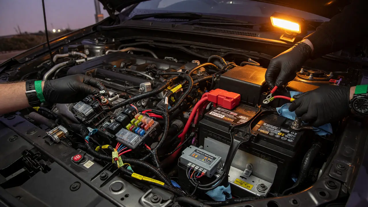
How to Safely Integrate Custom Electronics into a Car's 12V System
Learn proven methods for fusing, wire sizing, and power conditioning when integrating custom electronics into a vehicle's 12V system safely.
Car electrical systems leave almost no room for mistakes. One undersized wire or a fuse in the wrong spot can leave you stranded or, worse, start a fire. Follow proven rules for fusing, wire sizing, and power conditioning so your custom loads get clean power without issues.
Fuse Placement and Sizing Rules
Every positive feed needs protection right at the source. SAE J1284 and ISO 8820 both require the fuse to sit within 7 inches (18 cm) of the battery positive terminal or any distribution point. Negative returns stay unfused.
Size the fuse at 125% of the continuous load, but keep the actual draw under 75–80% of the fuse rating. Standard blade-type ATO/ATC or ATM fuses rated for 32 V DC work for most 10–20 A accessory circuits. Use slow-blow versions for motors and pumps that pull heavy inrush current.
Recommended fuse values for common loads
| Continuous Load | Fuse Rating | Wire Minimum (≤10 ft) |
|---|---|---|
| 5 A | 7.5 A | 16 AWG |
| 10 A | 15 A | 16 AWG |
| 15 A | 20 A | 14 AWG |
Selecting a Fuse Block or Power Distribution Module
A single, well-labeled fuse block makes future additions easier and holds up better to vibration. The Blue Sea Systems 5026 12-circuit ST Blade Fuse Block takes ATO/ATC fuses, handles 30 A per circuit and 100 A total, and uses #8-32 screw terminals plus #10-32 bus studs. Expect to pay $74–$97. The six-circuit split-bus versions (5023/5025 series) run $50–$80 and include a negative bus for tidy grounding.
Cheaper Amazon blocks under $30 exist, but they fail more often under heat and vibration. For most builds the Blue Sea units remain the safe choice.
Wire Gauge Selection for Short Runs
Both voltage drop and ampacity matter. On runs of 10 ft or less in normal conditions:
- 5 A circuits: 16 AWG is fine.
- 10 A circuits: 16 AWG works; step up to 14 AWG if the run sits in the engine bay.
- 15 A circuits: 14 AWG minimum; 12 AWG is better near heat sources.
Derate 20–30% when wires run through the engine compartment or travel in bundles. Keep voltage drop under 3% on anything critical.
Adding Regulated Power with DC-DC Converters
Modern electronics usually want clean, lower voltages. Wide-input buck converters shrug off load-dump spikes up to 36–40 V. The DFRobot 15–24 V → 12 V/12 A module runs above 95% efficiency, stays under 50 mV ripple, and includes overtemperature and short-circuit protection in a compact 30 × 26 × 8 mm package. Waterproof IP67/IP68 modules rated 50–480 W offer the same protections when the converter sits in an exposed spot.
Power flow architecture
graph TD
    Battery -->|7 in max| Fuse[Primary Fuse]
    Fuse --> FuseBlock[Blue Sea Fuse Block]
    FuseBlock -->|14-16 AWG| Converter[DC-DC Buck Module]
    FuseBlock -->|Direct| HighCurrentLoad[Lighting / Pumps]
    Converter --> RegulatedLoad[Sensors / ECUs]
Installation Checklist and Common Pitfalls
Follow this order on every install:
- Mount the fuse block close to the battery.
- Run properly gauged wire and use grommets through the firewall.
- Terminate with adhesive-lined heat-shrink connectors.
- Install the correctly sized fuse only after everything is connected and checked.
- Verify voltage drop under full load before you button things up.
Skip these shortcuts: tapping existing circuits without their own fuse, using chassis grounds that share paths with high-current loads, and leaving wires without strain relief where vibration is constant.
Solid fusing, correct wire sizing, and regulated conversion prevent most field failures. Builders who treat the 12 V system as a proper distribution network instead of an afterthought end up with installs that stay reliable for years.